
Have you ever wondered how HVAC ductwork is designed?
There are actually six methods for designing low, medium, and high-pressure HVAC systems:
- Equal Friction Method
- Static Regain Method
- T-Method
- Extended Plenum Method
- Velocity Reduction Method
- Constant Velocity Method
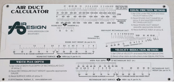
The most commonly used method is the Equal Friction Method. This method is typically used for low-pressure systems found in commercial buildings and is distinguishable by the fact that the pressure loss in the duct system per every 100 feet of duct is designed to be the same for the entire system. A well-designed system is typically designed to have an average friction rate of about 0.1” of water column per 100 ft. of duct length.
After the desired friction rate and cubic feet per minute (CFM) of airflow is determined for a system, an air duct calculator is used to properly size the ductwork that can support these requirements. The major disadvantage for the Equal Friction Method is that there is no provision for equalizing pressure drops in duct branches unless the duct layout is symmetrical.
Why Is Duct Design Important?
HVAC systems are comparable to cardiovascular systems; rooftop or air handling units are like the heart, and ductwork is similar to the body’s arteries and veins. Taking this example further, if arteries or veins are too big or too small, issues (such as high blood pressure or a stroke) can start to arise.
Similarly, if ductwork is incorrectly sized, vital issues to the units can arise. Having ductwork that is too large can lead to a low CFM (Cubic Feet per Minute) of air flow in a given space, which could cause the unit to run longer in order to properly heat or cool a space. Inversely, having ductwork that is too small can lead to high velocities and static pressures, creating a loud environment and putting unnecessary stress on the system.
Either direction you go — too big or too small — the system’s life span and energy expenses are both negatively impacted by having incorrectly sized ductwork. Having properly sized ductwork can lead to lower energy expenses, longer unit lifespans, and comfortable environments.
How Does a Melink Technician Verify Ductwork Installation?
While on site performing a Test & Balance, Melink technicians are trained to question if duct systems are installed correctly in the situation where proper airflow is unattainable, unless unit total speeds are further adjusted to deviate from the design.
When occurrences such as this happen, Melink technicians can reference the mechanical plans, a duct design table, or an air duct calculator to verify what the proper duct size should be for a given amount of air flow and compare that with the installed ductwork.
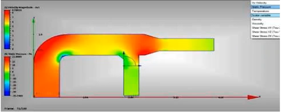
Melink technicians are also trained to look for and identify areas of dynamic losses, which are portions of ductwork that have high friction rates and high static pressure.
Examples of dynamic losses due to installation errors are incorrect duct take offs, failure to include duct turning vanes, long runs of flex duct, or crimped flex duct. These issues, if not corrected, can shorten the lifespan of the unit and cost the owner upwards of $1,200 per year extra in energy expenses. Any duct design discrepancies found in a Melink Test & Balance will be reported and photographed for the customer to reference.
Contributed by Andy Austin, Jeremy Neff & Anna Rusconi